
SeaWiFS Level 3 Monthly Chlorophyll a
Global Composite Browse Imagery
Summary:
The Sea-viewing Wide Field-of-view Sensor (SeaWiFS) is an eight-channel
visible light radiometer dedicated to global ocean color measurements which are
used to detect and analyze patterns of biological activity in the marine environment.
The mission parameters of SeaWiFS allow coverage of more than 90% of the ocean
surface every two days. SeaWiFS will map global ocean color at a resolution of
4.5 kilometers, and it also provides regional data at a resolution
of 1 kilometer. SeaWiFS is the follow-on mission to the Coastal Zone
Color Scanner (CZCS), and the predecessor to several ocean color satellite
sensors scheduled for deployment in the years 1998-2002.
Acknowledgment:
The requested form of acknowledgement for research publications utilizing
SeaWiFS ocean color data is:
"Ocean color data used in this study were produced by the
SeaWiFS Project at Goddard Space Flight Center. The data were obtained from the
Goddard Earth Sciences Distributed Active Archive Center under the auspices of the National
Aeronautics and Space Administration. Use of this data is in accord with the SeaWiFS Research
Data Use Terms and Conditions Agreement."
Table of Contents:
-
-
-
Sea-viewing Wide Field-of-view Sensor
-
- This dataset consists of satellite measurements of global and
regional ocean color data obtained by the Sea-viewing Wide Field-of-view
Sensor (SeaWiFS), in orbit on the OrbView-2 (formerly "SeaStar") platform. The
concentration and predominant identity of substances and particles in the
euphotic (lighted) zone of the upper ocean influences the apparent color of the
ocean, which can range from deep blue to varying shades of green and ruddy
brown. Living phytoplankton (which contain chlorophyll and associated
photosynthetic pigments), inorganic sediments, detritus (particulate
organic matter), and dissolved organic matter all contribute to the color of
the ocean.
 OrbView-2.
-
- A quantitative determination of global ocean primary productivity is
crucial to understanding the ocean's role in the global carbon cycle. The
SeaWiFS mission parameters were designed with this goal as a fundamental
consideration. In addition, SeaWiFS will refine remote-sensing measurements
of phytoplankton chlorophyll and associated pigments, organic matter,
and suspended particulate matter in the oceans. SeaWiFs will provide
the first continuous observations of global ocean color, anticipating
ocean color data from several future ocean remote sensing missions.
The Coastal Zone Color Scanner (CZCS) went far beyond its original
status as a proof-of-concept mission. During its eight years of operation
(November 1978-June 1986) the CZCS clearly demonstrated that measurements of
ocean color from space were possible, and also proved that this technology
could be used to characterize the distribution of biological productivity
in the surface ocean. CZCS mission constraints, however, prevented
quantitative determination of global ocean primary productivity.
NASA's ocean biogeochemistry research program, of which SeaWiFS
is a critical element, has established a set of science goals. Data from
SeaWiFS is expected to be used in the following ways:
- Goal I: Determine the spatial and temporal distributions of phytoplankton
blooms, along with the magnitude and variability of primary
production by marine phytoplankton on a global scale.
- Goal II: Quantify the ocean's role in the global carbon cycle and
other biogeochemical cycles.
- Goal III: Identify and quantify relationships between ocean physics
and large-scale patterns of biological productivity.
- Goal IV: Understand the fate of fluvial nutrients and their possible
effect on marine carbon budgets.
- Goal V: Identify the large-scale spatial and temporal distribution
of spring blooms in the global oceans.
- Goal VI: Acquire global data on marine optical properties, accompanied
by an improved understanding of processes associated with mixing
along the edges of eddies and boundary currents.
- Goal VII: Advance the scientific applications of ocean color data
and the technical capabilities required for data processing,
management, and analysis, in preparation for future missions.
One of the primary goals of the SeaWiFS Project is the following
stringent objective:
"To achieve radiometric accuracy to within 5% absolute and 1%
relative, water-leaving radiances to within 5% absolute, and
chlorophyll a concentration to within 35% over the range
0.05 - 50.0 mg m-3."
-
- Level 3 data consists of geophysical parameters binned to a 9x9 km (81
km2) global, equal-area grid at daily, 8-day, monthly, and annual
intervals. The Level 3 geophysical parameters consist of five normalized
water-leaving radiances (radiance data corrected for atmospheric light
scattering and sun angles differing from nadir), and seven geophysical
parameters derived from the radiance data. The following table lists the 12 SeaWiFS Level 3 geophysical
parameters.
	Normalized water-leaving radiances at:
	412 nm
	443 nm
	490 nm
	510 nm
	555 nm
	670 nm
	Chlorophyll a concentration
	Diffuse attenuation coefficient at 490nm, K(490)
	Chlorophyll a / K(490) (integral chlorophyll)
	Epsilon of the aerosol correction at 765 and 865 nm
	Aerosol optical thickness at 865 nm
	Angstrom coefficient, 510-865 nm
In addition to the Level 3 binned data, Standard Mapped Image (SMI)
products are created for five Level 3 binned data products.
The SMI products are image representations of five Level 3 geophysical
parameters: chlorophyll a concentration, Angstrom coefficent 510-865 nm, normalized water-leaving radiance at 555 nm, aerosol optical
thickness at 865 nm, and K(490). Each SMI product corresponds to the
equivalent Level 3 binned data file, i.e., a daily SMI product represents the
data from the Level 3 binned data file from the same day. The HDF data object
containing the geophysical parameter data is a byte-valued, two-dimensional
array for an Equidistant Cylindrical projection of the globe.
[ See Glossary of Terms for definitions. ]
-
- Technical aspects of visible wavelength remote sensing of the ocean
surface are discussed in this document.
-
- The primary precursor dataset to the SeaWiFS dataset is the eight-year
archive collected by the CZCS. Other ocean color datasets are from the
Ocean Color and Temperature Scanner (OCTS) and the
Modular Optoelectronic
Scanner (MOS). The
Moderate Resolution Imaging Spectroradiometer (MODIS)
is slated to begin operations in 1998, and several additional ocean color
sensors are slated for launch in the period 1997-2002. Data from the
Advanced Very High Resolution Radiometer (AVHRR), primarily used to observe
sea surface temperature but also employed to observe turbid water masses,
can be correlated with ocean color data. Sea surface wind datasets (derived
either from remote sensing, meteorological instruments, or meteorological
observations) can also be used in concert with ocean color data.
-
-
-
- Dr. Charles McClain, Project Scientist
- Goddard Space Flight Center, Code 970.2
- Greenbelt, MD 20771
- (301)286-5377
- Email: mcclain@calval.gsfc.nasa.gov
- Dr. Wayne Esaias, MODIS Oceans Team Leader
- Goddard Space Flight Center, Code 971
- Greenbelt, MD 20771
- (301)614-5709
- Email: wayne@puffin.gsfc.nasa.gov
- Dr. Stanford Hooker, Field Program Manager
- Goddard Space Flight Center, Code 971
- Greenbelt, MD 20771
- (301) 286-9503
- Email: stan@ardbeg.gsfc.nasa.gov
- Dr. Gene Feldman, Data System Manager
- Goddard Space Flight Center, Code 610.2.3
- Greenbelt, MD 20771
- (301)286-9428
- Email: gene@seawifs.gsfc.nasa.gov
- Data:
- Dr. Gene Feldman
- Goddard Space Flight Center, Code 610.2
- Greenbelt, MD 20771
- (301)286-9428
- email: gene@seawifs.gsfc.nasa.gov
- Software:
- Frederick Patt
- SeaWiFS Project, Code 970.2
- Goddard Space Flight Center
- Greenbelt, MD 20771
- (301) 286-2866
- Email: Frederick.S.Patt.1@gsfc.nasa.gov
-
- Sea-Viewing Wide Field-of-view Sensor (SeaWiFS) Project
-
- See above
-
- SeaWiFS data is primarily used to determine concentrations of
chlorophyll in the oceanic water column. These values may be used to derive
phytoplankton concentrations and oceanic primary productivity. The ocean
optical data from SeaWiFS can also be used to determine light attenuation in
the oceanic water column, which provides information on suspended sediment
concentrations and other parameters. Ocean color distribution can be used to
investigate the forces influencing trophic productivity in the world's oceans.
-
- Ocean color remote sensing is based on the principle that particulate
and dissolved substances suspended in water will interact with
incident light. Where concentrations of particulate matter and dissolved
substances are low, conditions typical for the open ocean,
water molecules scatter light similar to the way that the atmosphere scatters
light, producing a characteristic deep blue color. The scattering of light by
particulates and the absorption of light by dissolved substances will alter
this color. Chlorophyll, the photosynthetic pigment found in phytoplankton,
absorbs strongly in the red and blue regions of the visible light spectrum and
reflects in the green. As the concentration of phytoplankton increases,
the color of the water will therefore appear increasingly green. The
absorption of light by chlorophyll can be quantified to determine the
concentration of chlorophyll in water, allowing estimation of phytoplankton
abundance in a given area.
The relationship between light absorption and chlorophyll concentration may be
complicated by the presence of light-scattering inorganic particulate matter in
the water. Particulate matter concentrations generally increase in coastal
regions, such that the water color near the coast trends from green to brown or
reddish-brown. Even though chlorophyll may be present in higher concentrations
near the coast, the presence of particulate matter makes it more difficult to
extract the amount of light absorption due solley to chlorophyll. In addition,
certain classes of phytoplankton form hard mineral shells that scatter light
very effectively, such that the water color can appear shade of aquamarine or
milky white.
SeaWiFS measures light intensity in several bands. The measurements
allow quantification of light absorption and subsequent estimation of
chlorophyll and suspended matter concentrations. SeaWiFS improves on the
CZCS mission by having better bands for atmospheric correction (i.e.,
removing the effect of light scattering by the Earth's atmosphere), which
will particularly aid the estimation of chlorophyll and suspended matter
in coastal regions.
-
-
-
-
-
- The primary optics of SeaWiFS consist of an off-axis folded
telescope and a rotating half-angle mirror. Radiation backscattered by
the Earth's surface and atmosphere is collected by the telescope and
reflected onto the mirror, and the beam path is then directed through
beam splitters (dichroics, which transmit some wavelengths and reflect
the rest) to separate the radiation into four wavelength regions.
Spectral bandpass filters are used to narrow these regions to the 20 nm
requirements of the eight SeaWiFS spectral bands, and the radiation then falls
on silicon detector elements. The electronics module amplifies the detector
signal, performs analog-to-digital conversion and time delay and integration
for data transmission. Instrument calibration utilizes an on-board solar
radiation diffuser and lunar observation. The instrument may be tilted
forward or backward 20 degrees along the spacecraft orbital trajectory to
minimize the effects of sun glint.
 SeaWiFS
-
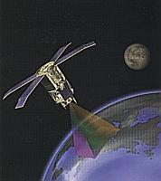
- The OrbView-2 satellite (formerly called "SeaStar") orbits in a
sun-synchronous, descending node orbit at an altitude of 705 km. The
orbital period is 98.9 minutes, with an inclination of 98.217 degrees.
Local time of descending node is 12:05 PM + 15 minutes.
The satellite was launched on August 1, 1997 into a 305 km orbit, and
32 orbit-raising burns performed over the next month raised the orbit
to its final altitude.
The satellite has a three-axis stabilized system consisting
of orthogonal magnetic torque rods for roll and yaw control and
two momentum wheels for pitch stabilization. The satellite is equipped
with sun sensors, horizon sensors, and magnetometers.
The propulsion system consists of two subsystems, a reaction control
system and a hydrazine propulsion system. The reaction control system uses
nitrogen and provides third stage stabilization during the launch. The
hydrazine propulsion system is used for raising the orbit from the nominal 278
km parking orbit to the 705 km sun-synchronous operational orbit. In addition,
it is used for orbit trim requirements over the life of the mission. The
spacecraft employs four Hamilton Standard one pound thrusters.
Redundant global positioning system (GPS) receivers are used for
orbit determination, an essential component of satellite and data navigation
(Earth location). The orbit state derived from GPS is
included in the spacecraft health telemetry.
Two telemetry streams are transmitted. The first is real-time LAC data
merged with spacecraft health and instrument telemetry at 665.4 kbps. This is
transmitted at L-band with a frequency of 1702.56 MHz. The other telemetry
stream consists of stored GAC and selected LAC, along with spacecraft health
and instrument telemetry, at 2.0 Mbps. This is transmitted at S-band with a
frequency of 2272.5 MHz. The command system uses S-band with an uplink of
19.2 kbaud at 2092.59 MHz.
-
- The primary mission objective of SeaWiFS and the Orbview-2 satellite is to
obtain a continuous five-year record of ocean radiance observations.
-
-
Nominal operating parameters for SeaWiFS:

	Scan Width		58.3 deg (LAC); 45.0 deg (GAC)
	Scan Coverage		2,800 km (LAC); 1,500 km (GAC)
	Pixels along Scan	1,285 (LAC);  248 (GAC)
	Nadir Resolution 	1.13 km (LAC);  4.5 km (GAC)
	Scan Period		0.167 seconds
	Tilt			-20, 0, +20 deg
	Digitization		10 bits
-
- Remote sensing instruments measure electromagnetic energy that is
either reflected or emitted from objects and surfaces. This
measurement technique can be termed either radiometry or
photometry, depending on the wavelength range of the energy
being measured. Radiometry refers to measurement of electromagnetic
radiation, ranging from X-rays to radio waves. Photometry refers
specifically to measurement of energy in the human optical wavelength
range. The terms "spectral radiometry" or "spectral photometry"
refer to measurements of energy defined per unit of wavelength.
-
- Refer to the schematic
diagram.
-
- Santa Barbara Research Center
(SBRC)
-
-
-
Pre-Launch Calibration
Due to the stringent radiometric objectives of the SeaWiFS Project,
SeaWiFS underwent an extensive prelaunch calibration program.
Calibration was performed at Hughes SBRC, and included an open
air observation of the Sun for solar calibration purposes. (The preflight
solar calibration is described in Chapter 3 of Volume 19 in the
SeaWiFS Technical Report Series, NASA Technical Memorandum 104566.)
The prelaunch characteristics of SeaWiFS were analyzed in detail
to provide a comprehensive understanding of the sensor's radiometric
response. SBRC employed a 100cm Spherical Integrating Source (SIS)
which with a spectral shape equivalent to a 2,850 K blackbody for
calibration purposes. Despite the approximate three-year hiatus between
instrument completion and spacecraft integration, the calibration
of the instrument was essentially unchanged over that time.
For further information, see Volume 22 of the SeaWiFS Prelaunch Technical
Report Series, "Prelaunch Acceptance Report for the SeaWiFS Radiometer".
-
-
IFOV, nadir, zero tilt: 1 - 1.21 km
Fore and aft pointing: 0, +20, -20 deg, 40 degree tilt change within 30s
Band tolerances: Band edges +/- 2 nm, stable to less than 1 nm
Out-of-band response: Less than 5% of within-band value for 100% reflectance
Band co-registration: Co-registration within 0.3 pixel
Sensitivity: SNRs to exceed: Band 1, 499; Band 2, 674; Band 3, 667; Band 4,
640; Band 5, 596; Band 6, 442; Band 7, 455; Band 8, 467.
Absolute radiometric accuracy: 5%
-
- SeaWiFS does not carry calibration lamps, but will rely on views
of a solar radiation diffuser and the moon for radiometric calibration.
The solar radiation diffuser is viewed once per orbit (near the southern
terminator) to monitor sensor calibration over several orbits. The
moon is viewed via a spacecraft maneuver to monitor calibration over months
or years. Lunar views take place when the lunar phase is few days prior to or
past full moon.
-
- Data validation is accomplished by comparing data from the sensor
to ocean optical data obtained during a series of calibration cruises, both
prelaunch (commencing in 1992) and soon after the launch of the satellite.
The data validation process also utilizes data from the
Marine Optical Buoy
(MOBY) moored off of the island of Lanai, Hawaii. MOBY is a moored in- and
above-water optical radiometer that can transmit data to a receiving station on
Lanai, allowing frequent comparison to data from SeaWiFS.
-
- Telemetry from the instrument is either transmitted
directly to ground High Resolution Picture Transmission (HRPT) stations or
recorded on the instrument for later transmission during downlink sessions to
GSFC. Direct broadcast data is 1 km resolution LAC data. Recorded data is
either 1 km resolution LAC data (primarily for calibration and validation)
and 4.5 km resolution GAC data. The GAC data is used for the production of
the global data set. Data is placed on disk and then processed to Level 1A,
Level 2, and Level 3 products by the SeaWiFS Project. The data are then
transmitted to the Goddard DAAC for archive and distribution. (HRPT data are
processed to Level 1A by the receiving station, then sent to the SeaWiFS
Project and subsequently to the DAAC.)
-
-
- SeaWiFS data consists of ocean radiances in 8 spectral bands and derived
geophysical products.
-
-
- Spatial coverage is global, with full GAC coverage (approximately 90% of the
ocean surface) every two days. Cloud cover prevents viewing of the
entire ocean surface on this time scale, so clouds are therefore apparent in a
daily Level 3 product, but in the 8-day and monthly binned products the
influence of clouds is significantly reduced. Coverage along the equator is
slightly degraded due to instrument tilt to avoid sun glint effects.

SeaWiFS Level 3 Daily Browse Image

SeaWiFS Level 3 Weekly Browse Image
-
- Level 3 Binned Geophysical Products:
Global, equal-area 9x9 km grid (81 km2)
Level 3 Standard Mapped Image Products:
Approximately 1° x 1° on an Equidistant Cylindrical map projection
Level 3 Browse Product:
Approximately 78 km at the equator (the browse image
is subsampled by a factor of 8 from the chlorophyll a SMI product).
-
- The binned product is mapped to an global equal-area grid. (See
below)
The SMI and browse products are mapped to an Equidistant Cylindrical Projection
of the globe.
-
- Level 3 binned data are stored in a representation of a global,
equal-area grid whose grid cells, or "bins", are approximately 9x9 km.
-
-
- Full-time operation of SeaWiFS began on September 18, 1997, such that the
first complete daily Level 3 product is on September 19, 1997. Daily Level 3
products prior to September 18 have partial global coverage. Full-time
operation of SeaWiFS obtains approximately 14.5 orbital swaths of data per
day.
-
- Level 3 Binned data products: daily, 8-day, monthly, annually
Level 3 Standard Mapped Image products: daily, 8-day, monthly, annually
-
-
- SeaWiFS Level 3 data products are derived from the Level 2 GAC product, which
in turn is derived from the Level 1A GAC data. The SeaWiFS Level 1A and Level
2 Guide Document describes Level 1A and Level 2 SeaWiFS data in detail. A
brief summary is provided below.
-
- SeaWiFS measures visible wavelength radiances for eight 20nm wide bands. The
bands are centered on the wavelengths given in the following table, along with
the primary use of data for that band.
 Band   Center Wavelength    	Primary Use
         nm    ("color")

  1     412   (violet)        	Gelbstoffe
  2     443   (blue)        	Chlorophyll absorption
  3     490   (blue-green)  	Pigment absorption (Case 2), K(490)
  4     510   (blue-green)      Chlorophyll absorption
  5     555   (green)           Pigments, optical properties, sediments
  6     670   (red)           	Atmospheric correction (CZCS heritage)
  7     765   (near IR)     	Atmospheric correction, aerosol radiance
  8     865   (near IR)      	Atmospheric correction, aerosol radiance
-
- SeaWiFS Level 3 data consist of the following
geophysical products. The units of measurement for the geophysical products
are included in this table.
SeaWiFS Level 3 Geophysical Products
|
| Parameter |
Description |
Units |
SMI |
| nLw_412 |
Normalized water-leaving
radiance @412 nm |
mW·cm-2·µm-2·sr-2 |
no |
| nLw_443 |
Normalized water-leaving
radiance @443 nm |
mW·cm-2·µm-2·sr-2 |
no |
| nLw_490 |
Normalized water-leaving
radiance @490 nm |
mW·cm-2·µm-2·sr-2 |
no |
| nLw_510 |
Normalized water-leaving
radiance @510 nm |
mW·cm-2·µm-2·sr-2 |
no |
| nLw_555 |
Normalized water-leaving
radiance @555 nm |
mW·cm-2·µm-2·sr-2 |
yes |
| nLw_670 |
Normalized water-leaving
radiance @670 nm
|
mW·cm-2·µm-2·sr-2 |
no |
| angstrom_510 |
Angstrom coefficient, 510-865 nm
|
dimensionless |
yes |
| chlor_a |
Chlorophyll a concentration
|
mg·m-3 |
yes |
| K_490 |
Diffuse attenuation coefficient
at 490 nm |
m-1 |
yes |
| chlor_a_K_490 |
Integral chlorophyll
[chlorophyll a divided by K(490)] |
mg·m-2 |
no |
| eps_78 |
Epsilon of the aerosol correction
at 765 and 865 nm |
dimensionless |
no |
| tau_865 |
Aerosol optical thickness
at 865 nm |
dimensionless |
yes |
-
- Goddard Space Flight Center
Distributed Active Archive Center (DAAC)
-
- SeaWiFS is planned as a five-year mission. The current data
begins on September 18, 1997 and continues to present.
-
- The browse images provided in this dataset document provide a visual
representation of SeaWiFS Level 3 data.
-
-
- Level 3 Binned data products: 13 files (1 main and 12 subordinate files)
Level 3 Standard Mapped Image products: 1 file (for a single parameter)
Binning Procedure
For the creation of a Level 3 binned data product, every valid measurement of
water-leaving radiance which falls within the latitude and longitude
boundaries of a given grid square is compiled within that bin. For the daily
Level 3 product, the net result is a subsampling of the Level 2 GAC data
by a factor of two, as no time binning is required. For the 8-day,
monthly, and annual Level 3 products, all of the valid measurements for the
given time period and grid square are compiled in the same bin and the
weighted mean of all observations is generated. The weight is based on the
number of valid pixels used in the binning process. The binning procedure is
described in detail in Volume 32 of the SeaWiFS Technical Memorandum Series,
"Level-3 SeaWiFS Data Products: Spatial and Temporal Binning Algorithms". (See
References.)
-
- All SeaWiFS data is available in Hierarchical Data Format (HDF), a
data format developed by the
National Center for Supercomputing Applications (NCSA).
HDF is a "self-describing" data format, which means that all of the information
necessary to examine the data in an HDF file is contained within the file.
HDF has several different "data models" which are used to store
data products. The data models that are used to store data are
Scientific Data Sets (SDS), Raster Image Sets, Vgroups, and
Vdatas. Global Attributes contain data that is applicable to the
entire data file. An entire HDF file may be visualized schematically
as a set of objects containing different data variables. Vgroups
act as directories to data arrays, and they can contain SDS objects. Vdatas
are list objects with data organized into fields within each Vdata, where each
field is identified by a unique field name.
HDF Structure of SeaWiFS Level 3 Binned Data
Each
SeaWiFS Level 3 binned data file actually consists of a main file and 12
subordinate data files. Each of the 12 subordinate data files contains the
data for one of the 12 Level 3 geophysical parameters. Both the main file and
the subordinate files are in the Vgroup "Level-3 Binned Data".
There are three Vdatas in the Level 3 main file:
SEAGrid, BinIndex, and BinList. Each of the Vdatas contains several fields that
describe the geographic binning scheme. The information in the level 3 main file is
essentially the metadata in common to all of the geophysical parameters as well
as metadata appropriate to Level 3 SeaWiFS data. Each of the 12 geophysical parameters is
in the Vgroup "Level-3 Binned Data" and is a separate Vdata. There are two
fields in a Vdata for a given geophysical parameter, indicated by the suffix
sum or sum_sq. These fields are stored as 4-byte floating point
quantities in the subordinate files.
(Refer to the PDF document SeaWiFS OPERATIONAL ARCHIVE PRODUCT SPECIFICATIONS for information on the
variables of each of these Vgroups.)
SeaWiFS Level 3 Global Attributes:
Mission and Documentation
	Product Name
	Title
	Data Center
	Station Name
	Station Latitude
	Station Longitude
	Mission
	Mission Characteristics
	Sensor
	Sensor Name
	Sensor Characteristics
	Product Type
	Replacement Flag
	Processing Time
	Software Name
	Software Version
	Processing Control
	Input Parameters
	Input Files
	L2 Flag Names
Data Time
	Period Start Year
	Period Start Day
	Period End Year
	Period End Day
	Start Time
	End Time
	Start Year
	Start Day
	End Year
	End Day
	End Millisec
	Orbit
	Start Orbit
	End Orbit
Data Description
	Latitude Units
	Longitude Units
	Northernmost Latitude
	Southernmost Latitude
	Westernmost Longitude
	Easternmost Longitude
	Data Bins
	Percent Data Bins
	Units
HDF Structure of SeaWiFS Level 3 Standard Mapped Image Data
The Standard Mapped Image (SMI) products have a much simpler HDF structure than
the Level 3 binned data. Each file consists of global attributes, the
byte-valued data array corresponding to one of the five geophysical parameters that are made
into an SMI product, and a palette array. The "Mission and Documentation" and
"Data Time" global attributes do not change from the corresponding binned data
file. However, "Data Description" is
now called "Scene Coordinates", and the "Data Description" fields are expanded.
The scaling information in the "Data Description" category is required to
convert the values in the array to actual geophysical parameter values. The
scaling equations for
each parameter are found in:
-
"SeaWiFS Science Algorithm Flow Chart
document", Michael Darzi,
Publisher: Greenbelt, Md. : [Springfield, Va. : National Aeronautics and Space Administration, Goddard Space Flight Center ; National Technical Information Service, distributor, 1998]
SMI Scene Coordinates
(Note: "SW" stands for "southwesternmost". This data element is used to
locate the grid squares.)
	Map Projection
	Latitude Units
	Longitude Units
	Northernmost Latitude
	Southernmost Latitude
	Westernmost Longitude
	Easternmost Longitude
	Latitude Step
	Longitude Step
	SW Point Latitude
	SW Point Longitude
SMI Data Description
	Data Bins
	Number of Lines
	Number of Columns
	Parameter
	Measure
	Units
	Scaling
	Scaling Equation
	Base
	Slope
	Intercept
	Data Minimum
	Data Maximum
File Naming Conventions for SeaWiFS Level 3 Data
The naming conventions for SeaWiFS Level 3 data describe the parameter, the
binning period, and the file type. Even though the file name appears complex,
it encapsulates all the necessary information to identify the file.
For a daily Level 3 binned data file generated on January 1, 1998, the file
name for one of the 12 subordinate files would appear as follows, showing the
Julian date (001) for the file:
S1998001.L3b_DAY.x##
The two-digit designation (##) in the suffix ranges from 00 to 11, denoting
the geophysical parameter. The DAAC appends the suffix "main" to the
designate the Level 3 main file and to distinguish it from the subordinate
(geophysical parameter) files. Thus, the corresponding main file name would be:
S1998001.L3b_DAY.main
The following table lists each suffix and the corresponding geophysical
parameter.
Geophysical Parameters and
Corresponding Level 3 File Name Suffix |
| Suffix |
Geophysical Parameter |
| .x00 |
nLw_412 |
| .x01 |
nLw_443 |
| .xO2 |
nLw_490 |
| .x03 |
nLw_510 |
| .x04 |
nLw_555 |
| .x05 |
nLw_670 |
| .x06 |
angstrom_510 |
| .x07 |
chlor_a |
| .x08 |
K_490 |
| .x09 |
chlor_a_K_490 |
| .x10 |
eps_78 |
| .x11 |
tau_865 |
For the 8-day, monthly, and annual Level 3 binned files, the file name will
show the start date and end date of the binning period, and a file type
designation. The file type designations are "8D" for the 8-day binned
product, "MO" for the monthly product, and "YR" for the annual product. As an
example, for an 8-day binned product with a start date of January 1, 1998
and end date of January 7, 1998, the file names would be
	S19980011998007.L3b_8D.x##
	S19980011998007.L3b_8D.main
For the SMI files, the binning period convention is the same as for the binned
products. The SMI products are designated with the suffix "L3m", and the file
type convention (DAY, 8D, MO, YR) is also the same for the binned products,
as the SMI files correspond to a parent binned product. The five parameters
are designated with the file name terminators "CHLO", "A510", "L555", "T865",
and "K490" for chlorophyll a concentration, Angstrom coefficent 510-865 nm,
normalized water-leaving radiance at 555 nm, aerosol optical depth at 865 nm,
and K(490), respectively. As an example, for the chlorophyll a SMI
product corresponding to the above binned product, the file name would be
S19980011998007_L3m_8D_CHLO
-
-
- The process of deriving accurate geophysical values from remote
sensing radiance data is conceptually simple yet operationally complex.
In principle, the instrument in space detects the intensity of light at
various wavelengths of the electromagnetic spectrum. In the case of
SeaWiFS, all of the wavelengths it detects are in the narrow segment of the
spectrum that is visible to the human eye. The sole function of the
instrument and its associated electronics is to quantify the light
intensity, translate it into digital form, append data that allows
the data to be navigated (i.e., determine the location on Earth from where
the light originated), and send it to an Earth-based receiving station.
The remainder of the data analysis takes place on Earth. Algorithms
developed on the basis of radiative transfer physics and
both oceanographic and meteorological observation are employed to accurately
extract the faint signal of backscattered light radiating from the ocean
surface from the pervasive influence of scattered light in the atmosphere, an
effect that is accentuated by the presence of atmospheric aerosol particles.
The CZCS employed the assumption that no light radiated
from the ocean surface at 670 nm, and thus all of the light detected was
due to Rayleigh scattering from air molecules and aerosol scattering. SeaWiFS
improves on this scheme by detecting light at 765 and 865 nm, as a small
amount of light may actually radiate from the ocean at 670 nm. Furthermore,
the atmospheric correction scheme used by SeaWiFS more accurately reproduces
variable atmospheric conditions (Gordon and Wang 1994).
Once the radiance signal has been corrected for atmospheric light scattering,
the signal is then corrected for the solar zenith angle to derive
normalized water-leaving radiances. Normalized water-leaving radiances are
subsequently used in algorithms to produce geophysical values. These
algorithms were developed through oceanographic research into the optical
characteristics of oceanic surface waters. As the most significant
influences on the optical nature of oceanic waters are the presence of
chlorophyll in phytoplankton and the presence of suspended particles, the
algorithms use the water-leaving radiances to calculate the values of the
related geophysical parameters. The geophysical parameters are calculated from
the radiance values on a pixel-by-pixel basis, allowing the values to be
mapped to Earth coordinates.
Several different methods have been employed to allow an accurate
continuous assessment of instrument calibration. These methods were
previously described in Section 5. The data analysis utilizes observations of
the onboard solar diffuser and of the nearly-full moon for onboard instrument
calibration. Data from the Marine Optical Buoy (MOBY) moored off of Lanai,
Hawaii, is used to monitor the accuracy of "system calibration", which
refers to the interaction of sensor data and scientific data processing
to derive geophysical values that approximate reality.
-
- SeaWiFS Level 0 data is digitized at 10 bits for transmission
to ground stations. The primary data elements in Level 0 data are the
raw radiance counts for all eight bands, accompanied by spacecraft and
instrument telemetry. Processing to Level 1A appends calibration and
navigation data to the file, as well as instrument and selected spacecraft
telemetry. There are several different forms of Level 1A data: HRPT
LAC, recorded LAC (which includes several types of calibration data), and
GAC. A single GAC file consists of a swath data recorded from one
north-to-south orbital pass, and constitutes one HDF file. A single HRPT
file contains all of the scans received by the ground station while the
satellite was above the station's receiving horizon. Recorded LAC scans,
which are usually recorded for calibration and validation purposes as well
as for regions of special research interest, contain the number of scan
lines ordered by Mission Operations to cover the designated region.
Processing to Level 2 requires several additional steps. The
data is navigated so that land masks may be correctly placed. Ancillary
meteorological data and ozone data is used for atmospheric correction.
The computational steps described earlier are employed to produce normalized
water-leaving radiances and derived geophysical products. Each Level 2
data file is one HDF file, and corresponds exactly in temporal and spatial
extent to the parent Level 1A file. Note that only Level 1A GAC data is
processed to Level 2. Recorded LAC and HRPT LAC data is not processed to
Level 2, but the SeaWiFS Data Analysis System (SeaDAS) which is discussed
further in the "Related Software" section, will be capable of processing
Level 1A data to Level 2 geophysical products.
The primary operation that is performed to create SeaWiFS Level 3 data products
is data binning. Binning is used to reduce the total volume of data,
creating reduced resolution files which are more useful for global or
basin-scale research. To create a binned data product, all of the valid
measurements of water-leaving radiance which fall within the latitude and
longitude boundaries of a given grid square are compiled within that bin.
Any pixel values that are masked are excluded, with the net result that over
longer binning periods, the influence of clouds is selectively eliminated.
The daily Level 3 product is only a spatial binning of the Level 2 GAC data
by a factor of two, to produce a 9x9 km global data product. No time binning
is required for the daily Level 3 product, and thus the cloud mask will still
be apparent. For the 8-day, monthly, and annual Level 3 products, all of the
valid measurements for the given time period and grid square are compiled in
the same bin and the weighted mean of all observations is generated. The
weight is based on the number of valid pixels used in the binning process.
Because the number of valid water-leaving radiance measurements increases with
longer binning intervals, the influence of clouds will be lessened,
producing cloud-free images. Note also that the variability of ocean color in
a given area will be averaged out over longer time intervals.
-
- The SeaWiFS Project will periodically reprocess the entire dataset during the course of the mission as the algorithms for the calculation of the geophysical products are refined. The current status of the algorithms may be found in: "SeaWiFS Science Algorithm Flow Chart", Michael Darzi,
Publisher: Greenbelt, Md. [Springfield, Va. National Aeronautics and Space Administration, Goddard Space Flight Center, National Technical Information Service, distributor, 1998]. Other processing changes may be required as the calibration of the instrument or the sensor operating environment vary over time.
Summaries of the processing changes which were implemented in each of the SeaWiFS data reprocessings can be accessed
on the
SeaWiFS Data Reprocessing Web page.
-
-
- Numerous effects can lead to anomalous radiance conditions which
influence the calculation of normalized water-leaving radiances and
derived geophysical parameters. In particular, highly turbid waters,
coccolithophore blooms, and sun glint provide anomalously high
water-leaving radiances. Clouds and ice are "bright targets" than can
influence adjacent pixels. Low sun angles also affect water-leaving
radiances.
Flags and masks that are used in SeaWiFS data processing are described in
detail in the Level 1A and Level 2 Data Set Guide Document. Flags are set
for data pixels that do not pass quality tests, indicating anomalous and
possibly erroneous data. The masks in the Level 3 product correspond to the
masks in the Level 2 products and correspond to one of five conditions: high
Lt, land, clouds or ice, sun glint, or atmospheric correction
failure. The field flags_set in the BinList Vdata describes all grid
squares for which flags were set in the parent Level 2 data file.
-
-
- Similar to other optical remote sensing instruments, SeaWiFS data
will be affected by the presence of clouds, particularly on a daily basis.
The weekly and monthly binned data products substantially reduce the
influence of clouds, but with a concomitant loss of temporal resolution
of oceanic features that change through time.
-
- The binning procedure gives particularly high weight to limited numbers of
observations. In areas where cloud cover or sea ice is pervasive, a single
valid pixel obtained during the temporal binning period can give a biased
indication of the actual parameter value for that region. As more
observations are compiled, this variability is reduced. Thus, data from areas
known to be affected by considerable cloud cover or sea ice should be
interpreted with caution.
-
- It is anticipated that the data from SeaWiFS will be augmented
by data from the
Moderate Resolution Imaging Spectroradiometer (MODIS),
launched in December 1999 on the Terra platform. Several other countries
have ocean color sensors in development that are slated for launch in the
period 1998-2002. The
Sensor Intercomparison and Merger for
Biological and Interdisciplinary Oceanic Studies (SIMBIOS) project was created
for the purpose of intercalibration of ocean color data obtained by different
ocean color instruments.
-
-
- Goddard DAAC Ocean Color Data and Resources Website
/OCDST/OB_main.html
Goddard DAAC Ocean Color Data Support Team
ocean@daac.gsfc.nasa.gov
James Acker, Team Lead
Code 610.2
NASA Goddard Space Flight Center
Greenbelt, MD 20771
USA
ocean@daac.gsfc.nasa.gov
301-614-5435
FAX: 301-614-5268
Goddard DAAC Helpdesk
Code 610.2
NASA Goddard Space Flight Center
Greenbelt, MD 20771
USA
help-disc@listserv.gsfc.nasa.gov
301-614-5224
FAX: 301-614-5268
-
- NASA Goddard Space Flight Center DAAC
-
- SeaWiFS data is obtained from the Goddard DAAC by establishing a SeaWiFS data subscription with the
DAAC. Use of the data browser allows researchers to select appropriate data products
and selection of data transfer options, either magnetic tape or FTP. The Ocean
Color Data Support Team must be contacted at ocean@daac.gsfc.nasa.gov to create a data
subscription. Data subscriptions automatically retrieve selected data products
as they are received from the SeaWiFS Project and prepare them for transfer on
magnetic tape (by mail delivery) or by FTP. Currently available tape formats
are 8mm EXABYTE tape (8200, 2.5 GB or 8500, 5 GB) or 4mm DAT tape (90m, 1.6
GB).
-
- The Goddard DAAC is the designated archive and distribution center
for all ocean color data obtained by NASA remote sensing missions.
-
- The SeaWiFS project is a "data buy" mission, for which NASA contracted with
Orbital Sciences Corporation to build and launch the satellite. In return,
Orbital Sciences Corporation was granted the opportunity to sell data from
SeaWiFS for commercial applications. From September 18, 1997 to March 11,
1998, data from SeaWiFS was unrestricted. After March 11, 1998, the data is
restricted to
SeaWiFS Authorized Research Users solely for scientific research
purposes. The data is subject to a two-week distribution embargo for normal
research applications. Rea-time data access is granted to researchers and
selected HRPT stations for specific research needs. After five years, all
SeaWiFS data will be unrestricted.
In order to restrict data access to SeaWiFS Authorized Research Users,
usernames and passwords are issued from the Goddard DAAC to each individual
research user after they have provided the
necessary documentation to the SeaWiFS Project.
-
-
- SeaDAS was specifically developed for the processing and analysis of
SeaWiFS HDF data. The following describes the what SeaDAS can do, as well
as providing a path to obtain the software.
The SeaDAS Web site, http://seadas.gsfc.nasa.gov,
is updated with current operating information for SeaDAS 4.0. System configuration and
hardware requirements, and information on how to obtain SeaDAS 4.0, are given
below and are also found on the SeaDAS Web site.
The SeaDAS software system was written for the specific purpose of analyzing and
processing SeaWiFS HDF data. SeaDAS is a comprehensive image analysis package for
all SeaWiFS data products and ancillary data (wind, surface pressure, humidity and ozone)
from NMC (National Meteorological Center and TOVS (TIROS Operational Vertical Sounder).
All SeaDAS source code is free and available for download via FTP.
The Interactive Data Language (IDL) from Research System Inc. (RSI)
is used to build all the GUI and display related programs in SeaDAS. SeaDAS 4.0 is released with
a blanket purchase of IDL-Runtime, so users do not have to acquire IDL or IDL-Runtime at
their expense. SeaDAS includes
the Hierarchical Data Format (HDF) libraries from National Center for Supercomputing Applications
(NCSA) which are also required to build certain SeaDAS programs. IDL, C, FORTRAN77,
and IMAKE from the vendors are required only if modifications to the source code and
user-defined versions of the executables are desired.
Suggested Hardware Requirements:
- Platform: SGI 02, SUN UltraSparc workstations, or PC
- Memory:192 MB (regular users), 384 GB (HRPT users)
- Disk: 9 GB (actual SeaDAS installation requires ~330 MB without demo files and
~950 MB with demo files. Additional disk space is required for storing original data and
processed data files.
- Tape Drive: 4MM(DAT) or 8mm Exabyte (for DAAC data)
- Display: 19" Console or X-terminal with 20 MB memory, 1280x1024 resolution, 8-bit, 256 colors
Software Requirements:
- Operating Systems: SGI: IRIX 6.3, or IRIX
6.5 SUN: Solaris 2.6 or Solaris 2.7
- Required Software: IDL-Runtime, IDL 5.1 or 5.2
- Languages: C (SGI V3.19, SUN V 3.0.1), FORTRAN(SGI V 4.0.2, SUN V
3.0.1), IDL 5.2 or 5.3 (IDL 5.1 may work but has not been re-tested)
- Software Libraries: HDF 4.1r1 (included in SeaDAS)
SeaDAS PC Linux Version
SeaDAS 4.0 for Linux/PC has been developed and tested under the following environment:
"Generic" PC with Pentium II 350 MHz CPU
Redhat Linux 6.0
IDL 5.1.2L for PC, IDL-Runtime
Compile-from-scratch support
- SGI: IRIX 6.3 and 6.5
- Sun: Solaris 2.6 and 2.7
- PC: RedHat Linux 6.0
Obtaining SeaDAS 4.0
SeaDAS is available for download via anonymous FTP from seadas.gsfc.nasa.gov.
The /seadas directory contains the following compressed tar files:
- seadas_data1.tar.Z, seadas_data2.tar.Z, seadas_data3.tar.Z: SeaDAS required data files for L1, L2, and L3 processing
- seadas_demo.tar.Z: sample files for testing, and demonstrations
- seadas_irix6.3.tar.gz: SeaDAS for SGI IRIX 6.3 operating system
- seadas_irix6.5.tar.gz: SeaDAS for SGI IRIX 6.5 operating system
- seadas_solaris2.6.tar.gz: SeaDAS for SGI IRIX 6.3 operating system
- seadas_irix2.7.tar.gz: SeaDAS for SGI IRIX 6.3 operating system
- seadas_rhlinux6.0.tar.gz: SeaDAS for PC, RedHat Linux 6.0 operating system
Connect to the SeaDAS ftp
site to download program files.
Note, some users, especially outside the U.S. have had trouble
with the size of large SeaDAS files. Smaller "split" sections of the files
have been created using the UNIX "split -20000" command. The split files can be found in the /seadas/split directory.
To put the split files back together (concatenate the files), use the following commands:
cat seadas_src.tar.Z?? > seadas_src.tar.Z (for source
tar file), OR
cat seadas_data.tar.Z?? > seadas_data.tar.Z (for data
tar file)
To put the pieces back together, and uncompress them, and unTAR the
TAR file in one step:
cat seadas_src.tar.Z?? | zcat - | tar xvf - (for source files)
OR
cat seadas_data.tar.Z?? | zcat - | tar xvf - (for data files)
SeaDAS can also be created on 4mm (DAT) or 8mm tape for those users who
do not have Internet access or who have substantial difficulty with FTP of
these large files. Please send your request to seadas@seadas.gsfc.nasa.gov.
Other HDF Software
SeaWiFS data has been successfully opened and examined using the
Fortner Research prototype HDF Browser, available for download. The
Research Systems Inc. software products Transform
and Noesys (descriptions can also be found at the SciSpy Web site) have been used on
SeaWiFS data files, and Noesys has been used to transfer SeaWiFS data to the EASI/PACE
Geographical Information System (GIS) software package.
Two other software packages, HDF Explorer and Windows Image Manager, have
also been used with SeaWiFS data files. Links to the sites where more
information can be obtained are below. Windows Image Manager offers the capability of
converting SeaWiFS data to many other image formats.
HDF Explorer
Windows Image Manager
-
-
- Aiken, J., G.F. Moore, C.C. Trees, S.B. Hooker, and D.K. Clark, 1995:
The SeaWiFS CZCS-Type Pigment Algorithm.
SeaWiFS Technical Report Series, Volume 29, NASA Technical Memorandum
104566, S.B. Hooker and E.R. Firestone Eds., NASA Goddard
Space Flight Center, Greenbelt, Maryland, 34 pages.
- Barnes, R.A., W.L. Barnes, W.E. Esaias, and C.R. McClain, 1994: Prelaunch
Acceptance Report for the SeaWiFS Radiometer.
SeaWiFS Technical Report Series, Volume 22, NASA Technical Memorandum
104566, S.B. Hooker, E.R. Firestone, and J.G. Acker, Eds., NASA Goddard
Space Flight Center, Greenbelt, Maryland, 32 pages.
- Biggar, S.F., P.N. Slater, K.J. Thome, A.W. Holmes, and R.A. Barnes,
1994: "Chapter 3: Preflight Solar-Based Calibration of SeaWiFS", IN:
McClain, C.R., R.S. Fraser, J.T. McLean, M. Darzi, J.K. Firestone, F.S. Patt,
B.D. Schieber, R.H. Woodward, E-n. Yeh, S. Mattoo, S.F. Biggar, P.N. Slater,
K.J. Thome, A.W. Holmes, R.A. Barnes, and K.J. Voss, 1994: Case Studies for
SeaWiFS Calibration and Validation, Part 2,
SeaWiFS Technical Report Series, Volume 19, NASA Technical Memorandum
104566, S.B. Hooker, E.R. Firestone, and J.G. Acker, Eds., NASA Goddard
Space Flight Center, Greenbelt, Maryland, 25-32.
- Campbell, J.W., J.M. Blaisdell, and M. Darzi, 1995: Level-3 SeaWiFS Data
Products: Spatial and Temporal Binning Algorithms,
SeaWiFS Technical Report Series, Volume 32, NASA Technical Memorandum
104566, S.B. Hooker, E.R. Firestone, and J.G. Acker, Eds., NASA Goddard
Space Flight Center, Greenbelt, Maryland.
- Brown, C.W., and J.A. Yoder, 1994: Coccolithophorid blooms in the global
ocean. J. Geophys. Res., 99, 7467-7482.
- Gordon, H.R., and M. Wang, 1994: Retrieval of water-leaving radiance and
aerosol optical thickness over the oceans with SeaWiFS: a preliminary
algorithm. Appl. Opt., 33(3), 443-452.
- Morel, A., 1988: Optical modeling of the upper ocean in relation to
its biogenous matter content (Case I waters). J. Geophys. Res.,
93, 10,749-10,768.
-
-
-
aerosol:
a suspension of fine solid or liquid particles in gas
albedo:
reflective power, i.e., the fraction of incident radiation (as light)
that is reflected by a surface or body
algorithm:
a step-by-step procedure for solving a problem or
accomplishing some end especially by a computer
ancillary:
supplementary (ancillary data with regard to SeaWiFS refers to
data from other sources that is used in data processing)
backscatter:
the scattering of radiation or particles in a direction opposite to that of
the incident radiation due to reflection from particles of the medium
traversed, or the actual radiation due to this process
bathymetry:
water depth measurements in a given body of water
bloom:
a rapid increase in the population and concentration of phytoplankton
boundary current:
large strong surface ocean currents that occur on the margins of ocean
basins, usually flowing parallel to a continental coast
chlorophyll:
photosynthetic pigment found in plants. Chlorophyll a is a green
pigment.
coccolithophore:
phytoplankton which creates external microscopic calcium carbonate hard
plates (coccoliths)
descending node:
the point at which an orbiting body rises through the plane of the ecliptic
traveling southward
downlink:
a communications channel for receiving transmissions from a spacecraft;
eddy:
a feature of ocean circulation where the direction of circulation is
circular or elliptical
electromagnetic spectrum:
the entire range of wavelengths or frequencies of electromagnetic
radiation extending from gamma rays to the longest radio waves and
including visible light
euphotic:
of, relating to, or constituting the upper layers of a body of water into
which sufficient light penetrates to permit growth of green plants
fluvial:
related to streams or rivers
gelbstoffe:
Dissolved and suspended inorganic matter, commonly found in river
discharge, which gives it a yellowish color. (from German:
"yellow substance")
inclination (orbital):
the angle between the orbital plane and the Earth's equatorial plane,
as measured in degrees
interpolation:
to estimate values of (a function) between two known values
irradiance:
the density of radiation incident on a given surface, irrespective
of direction
mask:
a single data value that indicates the presence of a particular
condition
nadir:
the point on the Earth directly below an orbiting satellite.
optical thickness:
the normalized extinction coefficient due to absorption and scattering
by intervening substances or particles in a direct beam of light
period:
the time interval required for the completion of one orbit by a satellite
photosynthesis:
the process by which chlorophyll-containing cells in plants convert incident
light to chemical energy and synthesize organic compounds from inorganic
compounds, especially carbohydrates, from carbon dioxide and water, with the
simultaneous release of oxygen.
phytoplankton:
free-floating photosynthetic organisms existing in aquatic environments
primary productivity
the rate at which organic carbon is produced photosynthetically.
radiance:
electromagnetic energy per unit time, area, solid area and spectral
band, i.e., electromagnetic energy radiating in a given direction
radiometer:
a device that detects and measures electromagnetic radiation in discrete
spectral bands of the electromagnetic spectrum.
resolution
In a spatial sense, the size of the smallest feature recognizable using the
detector.
spectral band:
a narrow range of the electromagnetic spectrum.
sun glint:
sunlight that is directly reflected from the water surface back
to the observer or detector
terminator:
the dividing line between the illuminated and the unilluminated part of the
moon's or a planet's disk
turbidity:
substances or particles that obscure light transmission
visible light:
Electromagnetic radiation with wavelength in the 390 to 770 nm range.
zenith:
the "sky" point located directly above an Earth-based sensor.
-
-
AVHRR	Advanced Very High Resolution Radiometer
CZCS	Coastal Zone Color Scanner
DAAC	Distributed Active Archive Center
FTP	File Transfer Protocol
GAC	Global Area Coverage
HDF	Hierarchical Data Format
HRPT	High Resolution Picture Transmission
LAC	Local Area Coverage
MOBY	Marine Optical Buoy
MODIS	Moderate Resolution Imaging Spectroradiometer
MOS	Modular Optoelectronic Scanner
NASA	National Aeronautics and Space Administration
NCSA	National Center for Supercomputing Applications
OCTS	Ocean Color and Temperature Scanner
SBRC	Santa Barbara Research Center
SDS	Scientific Data Sets

SIMBIOS	Sensor Intercomparison and Merger for Biological and
		Interdisciplinary Oceanic Studies

SIS	Spherical Integrating Source
SeaDAS	SeaWiFS Data Analysis System
SeaWiFS	Sea-viewing Wide Field-of-view Sensor
-
-
Change History
- Version 2.0
- Version baselined on addition to the GES Controlled Documents List, January 25, 1999.
- Version 2.0
- Version 2.0 editing completed June 22, 2000. Primary changes concerned new
geophysical data products
|
 |

